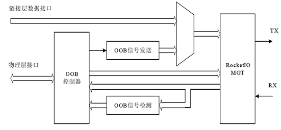
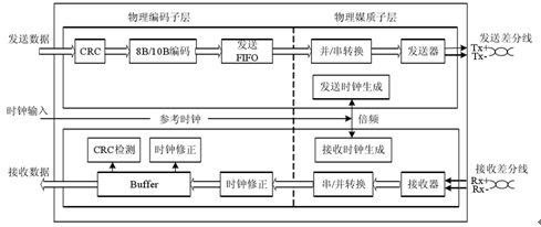
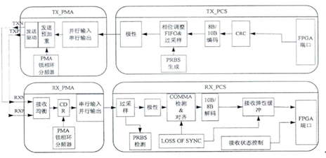
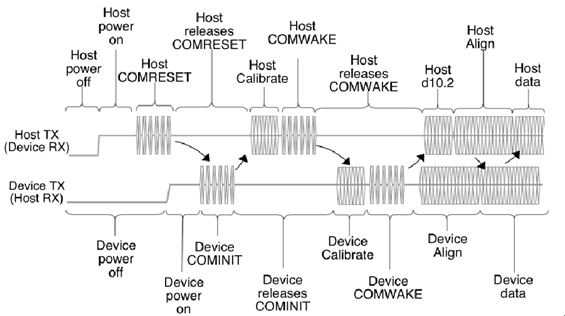
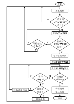
In the previous five articles, we briefly analyzed the contents of the SATA protocol. It can be seen that compared with the PATA protocol used by the parallel port hard disk, the SATA technology is more complicated, and there are many data processing links and various processing methods. Previously, with an 8-bit single-chip microcomputer, you can use the PIO method to read and write IDE hard disks by using two port ports. But for SATA hard drives, you can't use this method. High-speed serial signals, 1.5Gbps, 3.0Gbps, 6.0Gbps, the speed is too fast, think about how fast the CPU is. So for such a high speed, how to achieve offline reading and writing of SATA hard disk? One way is to design ASIC, this cost is too high, the price is too bad. One way is to use SATA to PATA bridges, such as Marvell and JMicro bridge chips, the advantage is simple, the disadvantage is that the speed is not fast, you want PATA is only 133MB / s, and SATA minimum 150MB / s. So the best way to cost-effective is to use FPGA to implement SATA interface, FPGA as Host, SATA hard drive as Device, offline read and write SATA hard drive. As a general-purpose chip, FPGA is still handy for handling such high-speed interfaces. Gigabit Ethernet, FC, and PCIE are all in the air. At present, high-end FPGAs integrate high-speed transceivers such as GTP and GTX. With these high-speed transceivers, the physical layer front end of SATA can be realized. Below, we will do a detailed analysis and introduction of the physical layer implementation of the SATA interface. The physical layer of the SATA protocol uses high-speed differential signals for data transmission, supports OOB signals, and has a physical layer rate of 1.5-6.0 Gbps. It cannot be implemented using ordinary I/O on an FPGA, and special devices need to be used for design requirements. At this stage, many FPGA companies design FPGAs with hard cores to support high-speed serial transmission. Xilinx's Virtex5 series is one of them. Rocket IO is a flexible, configurable thousand integrated in the Virtex5 series. Megabit serial receiver/receiver, in which LXT series integrated GTP transceiver supports data transmission rate of 600Mbps~3.125Gbps, FXT series integrated GTX transceiver supports data transmission rate of 500Mbps~6.5Gbps, and Rocket IO Supports the OOB signal of the physical layer of the SATA protocol. Therefore, the Rocket IO can be ideally applied to the implementation of the physical layer of the SATA protocol. The overall block diagram of the physical layer is shown in Figure 1. It mainly includes the implementation of high-speed serial link and OOB control module. The high-speed serial communication of physical layers of 1.5Gbps and 3.0Gbps can be realized by the integrated Gigabit transceiver Rocked IO MGT of Xilinx's Virtex-5 FX chip, providing a 20-bit wide parallel data interface. The OOB control module implements the detection and transmission of the OOB signal through the logic state machine to establish the communication connection. The physical layer interface module provides a standard access interface to the link layer. Figure 1 Physical layer structure RocketIO used in the physical layer consists of a physical medium attached sublayer (PMA) and a physical coding sublayer (PCS). The main internal functional block diagram is shown in Figure 2 and Figure 3. The PMA includes a serializer/deserializer (SERDES), TX and RX input/output buffers, a clock generator, and a clock recovery circuit. The PCS includes an 8B/10B encoder/decoder, a scrambler/descrambler, and an elastic buffer that supports channel bonding and clock correction. Figure 2 RocketIO internal structure 1 Figure 3 Figure 2 RocketIO internal structure 2 The complete GTP_DUAL consists of GTP0 and GTP1, and the above is only the structure of GTP0. GTP1 is the same, and modules such as clock reset are shared in the middle to save area and power consumption. The upper end is the receiving end, and the internal end is tested when it is not connected to the hard disk, as shown by the dotted line. Connect the transmit differential port to the receiver to verify that the parallel data at the receiver is consistent with the sender. PMA is a Physical Media Attachment, which refers to a sub-layer of physical media and is a key device for high-speed operation of transceivers. Built-in serial-to-parallel conversion module, serial clock up to 20 times the parallel clock, implemented with phase-locked loop (PLL). Since the higher the frequency, the more severe the signal attenuation, the transmit pre-emphasis and the receive equalization are used to compensate for the high frequency components of the signal to maintain signal integrity. The CDR is a clock data recovery circuit for Clock Data Recovery, which uses phase-locked loop technology to extract clock information from the serial code stream. Another part of the PCS is the Physical Coding Sublayer, which refers to the physical coding sublayer, and encodes the parallel code stream. The COMMA character is the first byte of ALIGN. It contains the COMMA sequence, which is the first seven digits of the character, 0101111 or 1100000. Detecting this character helps identify the correct byte boundary. PRBS is a pseudo-random binary sequence that tests the bit error rate of the data. The 8B/10B encoding and CRC check are not described here. All of the functional options are marked in Figure 3 and can be freely configured according to system requirements. The SATA physical link establishes the connection process: (1) The host is powered on, and the host sends a COMRESET signal for hardware reset, after which the physical link enters an idle state; (2) The device is powered on, and the device receives the COMRESET signal and sends a COMINIT signal after detecting that the physical link is released; (3) After receiving the COMINIT signal, the host first debounces the received signal. When it is confirmed that the COMINIT signal is detected, the host sends a COMWAKE signal, and then releases the link; (4) After receiving the COMWAKE signal sent by the host, and transmitting the COMWAKE signal when the link is idle; (5) After transmitting the COMWAKE signal, the device transmits the ALIGNp primitive at the highest supported speed, after which the device starts to wait for the ALIGNp primitive sent by the host; (6) The host detects the COMWAKE signal sent by the device, and after waiting for the bus to be idle, the host starts to send D10.2 characters, waits for 873.8μs of the ALIGNp primitive from the device, and after receiving the ALIGNp primitive, according to the received ALIGNp original To determine the link speed, and then send the ALIGNp primitive at a determined speed. Then, if three consecutive non-ALIGNp primitives (starting with K28.3) from the device end are received, the link establishes the connection and the host starts to send from Link layer data, and maintain this state, if the host waits for 873.8μs and still does not receive 3 non-ALIGNp primitives, the host considers that the current link initialization fails, and the host restarts the link layer initialization; (7) The device waits for the ALIGNp primitive from the host. When it waits for 54.6μs and still does not receive the ALIGNp primitive, the device lowers the speed mode, resends the ALIGNp primitive, and repeats this operation until it receives the original ALIGNp sent by the host. After that, the device starts to send data from the link layer. If the ALIGNp primitive is still not received after waiting for 54.6μs in the lowest speed mode, the device considers that the current link is initialized incorrectly, and the device performs error processing and then enters the idle state. . Figure 4 physical layer initialization process SATA physical link initialization process is implemented: Xilinx's FPGA development tool ISE provides GTP generation wizard, which can realize the physical layer definition function of SATA protocol. Due to the abundant storage resources on the FPGA, the OOB signal is sent in advance to solidify ALIGN in the memory, and then control the memory read time. And the interval to complete. Therefore, the most important task of using the FPGA to implement the SATA protocol physical layer is to design the joint logic, control the GTP to complete the SATA protocol initialization function, and design the SATA protocol initialization flow chart as shown in Figure 5. The initialization process needs to be done in strict accordance with the agreement and with the host. The device first detects the COMRESET signal after power-on. When the COMRESET signal is detected and the link is idle, the COMINIT signal is sent and the host responds. When the host response is not received for more than 10ms, the device returns to the device. In the power-on reset state, if the COMWAKE signal sent by the host is detected within 10ms, and the host releases the transmission signal line, the device initiates a COMWAKE signal to the host, and then the device sends the synchronization primitive ALIGNp at the highest supported rate, and then waits for the host to return. If the ALIGNp primitive does not detect the ALIGNp primitive sent by the host within 54.6μs, the device enters the reduced mode state and reduces the transmission rate. If the current transmission mode is the lowest transmission mode, the device initialization fails, processing error and returning. In the power-on reset state, if the current device is not in the lowest transmission mode, the device reduces the rate and restarts sending the ALIGNp primitive. When the ALIGNp primitive sent by the host is detected, the device establishes a connection with the host, and the SATA physical link The initialization is successful and then the interaction of the data frames can begin. Figure 5 SATA physical layer initialization flow chart Rocket IO GTP is selected as the SATA protocol physical layer high-speed serial data transceiver to simplify the design process of the SATA physical layer. By analyzing the SATA protocol physical layer link to establish the connection process, the OOB signal control state machine can be designed, and the SATA protocol initialization function is implemented by the FPGA to control the Rocket IO GTP to realize the function of the SATA physical layer. In short, the implementation of the SATA physical layer is the two key points of configuring the GTP and designing the OOB signal processing state machine. After processing these two points, the physical layer of the SATA interface can be realized. In the following articles, the implementation methods and techniques of the link layer, transport layer, command layer and application layer of SATA will be introduced one after another. About Darth Technology Dasi Technology, a national high-tech enterprise, the only collaboration unit for the data recovery of the confidentiality of the Tianjin National Secrecy Bureau, a well-known brand in the data recovery and forensics industry, is a technology-based enterprise with technology research and development as its core productivity, at home and throughout Asia. Data recovery and forensics technology leading! Darth Technology China data recovery and forensics experts! More data recovery and forensics technology, Internet, please pay attention to WeChat public subscription number: woocs Micro signal: woocs Long press to identify the QR code Focus on data recovery and forensics technology, the Internet Submission: Oversized/Appliance Pulls, hjypull.com offers more than 2000 pieces new design selection of products per Month. Appliance Pulls Shenzhen Hongjingyuan Metal&Plastic Products Co., Ltd. , https://www.hjypull.com