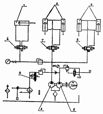
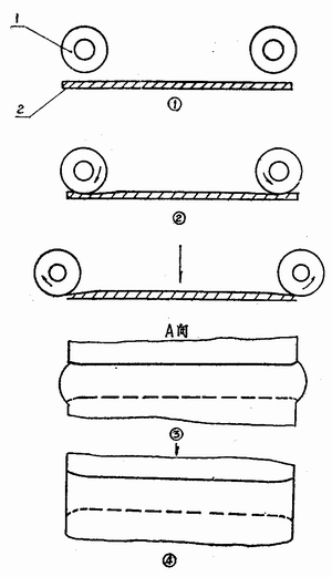
Barrel weld seam thinning trimming machine (2) 3602 Factory Tan Xinhua 3. Trimming machine adjustment 1 The extrusion squeeze of the squeeze wheel is achieved by the squeeze wheel. Therefore, if the extruded weld does not reach the required size, the hand wheel on the extruder can be rotated, and the squeeze wheel can be adjusted or lowered by the worm worm wheel and the eccentric shaft to achieve the required size. Can be adjusted freely within the range of 0-3mm. 2 Adjusting the trimming edge Cut the excess metal by JJ. When adjusting the tool, first loosen the tightening bolts and adjust the two) J-edge to O. according to the thickness of the sheet. 03~0.07mm. After adjustment, tighten the bolts and fix the 9 pieces. The length of the 8 barrels is different for different lengths of steel barrels. The pressure barrel is made by the oil cylinder. Since the stroke of the cylinder is fixed, it is necessary to adjust the distance to fit the length of the barrel to make the barrel tight. The adjustment method is to let the pressure cylinder extend, and loosen the lock nut at the end position of the pressure barrel, and turn the cross wheel of the cylinder and the sliding support to achieve the purpose of adjustment (adjustment or adjustment). After adjusting, lock the nut to fix its position. 4Feed adjustment The structure of the trimming machine requires that the axis of the barrel be aligned with the center axis of the press barrel as the correct feeding position. In this way, the trimming action of the press barrel can be ensured. This requires proper adjustment of the barrel feeding mechanism. 5 The hydraulic system of the machine tool adjusts the hydraulic system pressure by adjusting its relief valve to achieve the required working pressure. The pressure adjustment must be appropriate. If it is too small, the cylinder force is not enough. Too high is likely to cause the machine body to shake and cause an accident. Different materials, different specifications of the barrel, the appropriate pressure values ​​are different. 4. Trimming machine maintenance 1 Move the joints, be sure to add lubricant regularly, often check the oil mark, check the oil level of the oil pool. When the amount of oil is insufficient, it should be replenished in time. When adding new oil, it should be filtered. 2 Cut off water, electricity and gas before servicing equipment. 3 Clean the equipment after each shift to remove dust to ensure its service life and accuracy. 4 Frequently check: Whether the handle is in the correct position; whether the screw screw of the locking part is locked in each part; whether the sensing switch is in the correct position; whether the cylinder and the cylinder stay in the original position; check the inside and outside of each mechanism for obstacles. 5. Easy troubleshooting 1 The pressing force is not enough. The general reason is that the hydraulic system has a leak or the oil pressure is too low. If there is a leak, repair or replace the seal. If the pressing force is not enough, check the oil pump and tank level. 2 The extrusion action is not accurate, and it is good or bad. It can check whether the sliding sleeve of the relevant part is worn or not, and whether the fixing screw is loose, it should be replaced and adjusted in time. 8 cut and continue to cut. If there is an adjustable tool, check if the 9 positions are loose. If the tool is passivated due to wear, it should be sharpened, installed, and adjusted. 4 Action program failure (cannot operate according to normal program or malfunction), can check whether the non-contact sensor switch is damaged or the fixing screw is loose to change the position; if it is damaged, replace the sensor switch, the fault is eliminated if the screw is loose The position changes and the retightening fault can be eliminated. In addition, the control buttons such as start and stop, the switch is in poor contact, the programmable controller is disturbed or damaged, and the action may be out of control or not working. 6. Introduction to the trimming machine gas path and liquid system Figure 11 and Figure 12 are schematic diagrams of the pneumatic and hydraulic circuits of the trimming machine. Figure 11 Schematic diagram of the trimming machine pneumatic system 1- discharge cylinder (ie, de-cylinder cylinder); 2-belt cylinder; 3, 4- solenoid valve; 5-gas source three-piece. Figure 12 Schematic diagram of the trimming machine hydraulic system 1-pressure barrel cylinder; 2-extrusion cylinder; 3-cutting cylinder; 4-small flow oil pump; 5-high flow oil pump. In Fig. 11, the member 1 is a single-acting single-piston rod cylinder, and the member 3 is a two-position five-way solenoid valve. When the air supply is turned on, the discharge cylinder is in the original position (no discharge). In the automatic state, when the trimming action is completed, the solenoid valve is retracted, the electromagnetic valve is energized, and the B-way is ventilated, so that the discharge cylinder is completely unloaded, and when the electromagnetic valve is de-energized, the discharge cylinder is restored. The piece 2 in Figure II is a QGL type cable cylinder. It outputs the cylinder force with the pulling force of the cable. This cylinder is used as a feed in the trimming machine. It is the first action of a trimming machine in a working cycle. When the machine is in the initial state in the automatic working state, press SB5 or SB6, the solenoid valve 4 is energized, the air source is connected to the A port, and the B port is connected to the atmosphere. The feeding cylinder starts to feed. When it is delivered to the position, the valve 4 is de-energized, the B port is connected to the gas source, and the A port is connected to the atmosphere, and the cylinder drives the feeding frame to resume, waiting for the next working cycle to start. As can be seen from Figure 12, the hydraulic system uses a composite pump with a relief valve, a check valve, and an unloading valve. The purpose of the composite pump is to make the hydraulic system actuator, the cylinder, capable of two-speed movement according to working conditions - fast and slow. For the pressure cylinder, from the original position to the adjacent workpiece, it needs to move quickly, from the adjacent workpiece to the pressure bucket, it should be slow forward (ie, work in progress). It is required to quickly reset the pressure cylinder, and the slow-feeding is required before the bone-cylinder cylinder is completed from the origin to the completion of the bone. After the bone is finished to the reset, the quick-retraction is used from the origin to the cutting edge, the trimming cylinder adopts the work advance, and the reset is used to rewind. When the cylinder moves rapidly, the valve 10 circuit is closed, and the pressure oil of the large and small flow oil pumps supplies oil to the system, so that the corresponding cylinder moves rapidly. When the valve 19 is opened, the large flow pump 5 is unloaded. Therefore, the oil output from the large-flow oil pump flows directly back to the fuel tank, and only the small-flow oil pump supplies oil to the corresponding oil cylinder to realize the relevant action to achieve the work. The pressure of the small flow pump is controlled by valve 9 to maintain the necessary operating speed. The transition of the operating direction of each cylinder is controlled by a corresponding reversing valve. 7. Brief introduction of the thinning and trimming process of the weld seam thinning machine The schematic diagram of the thinning and trimming process of the weld bead trimming machine is shown in Fig. 13. Figure 13 Schematic diagram of the thinning and trimming process 1- squeeze wheel; 2- barrel frame edge section. In Fig. 13, 1 is the barrel frame in place, and the two pressure rings have pressed the barrel frame more than 2 to press the squeeze wheel to start pressing the barrel frame under the driving of the squeeze cylinder; 3 is the end of the pressing process, and the squeeze wheel is in the The displacement is driven by the squeeze cylinder. The figure below shows the top view of the weld after the weld is thinned. It can be seen that there are many iron tongues appearing as the top view of the iron tongue after being cut off. At this point, a working cycle of the trimming machine ends. Third, localization and problems that must be paid attention to during use The above is a relatively mature thinning and trimming equipment. At present, there are similar products in China. We should know that this machine is the middle section of RMG's automatic welding machine. Some of its performance parameters are designed according to the weld condition of the automatic welder. We know that the weld thickness welded by the automatic welder is similar to the thickness of the frame. According to China's standards, such welds can achieve the assembly effect of minimal leakage in the triangle even if they are not thinned. Therefore, the function of the thinning trimming machine designed for the weld seam of the automatic welder is to simply “symbolically†thin the weld and cut off the iron tongue. In China, in order to reduce the leakage of the triangular area, it is really necessary to press the thin cut. The side should be the welded seam obtained by the semi-automatic welding machine widely used by most manufacturers in China. We know that the semi-automatic weld seam edge size is generally 12-16mm, and the automatic welder weld seam edge is about 3-5mm. Obviously, If the thickness is reduced to the same thickness, the pressure required for the semi-automatic weld is about 4 times larger than that of the automatic weld. If the difference between the compression process of the two welds and the deformation mechanics are considered, this multiple is probably doubled. The thinning trimming machine that is suitable for foreign countries is used in the Chinese barrel industry with more backward semi-automatic seam welding machines. Because of the excessive difference between the cylinder crushing force and the rigidity of the fuselage, the thinning effect Obviously it is minimal, and the actual use proves this. Therefore, the middle-end equipment should adapt to the consensus of the barrel-making process. In the barrel-making factory with the domestically manufactured trimming machine, there is a reversal of reversal, that is, Shrink The length of the barrel body, reduce the value of the weld edge to adapt to the edge trimming machine. For example, some barrel manufacturers reduce the edge value to 8-lOmm. At this time, the extrusion trimming effect may be improved (but not too Large), but due to the reduction of the amount of edge, in the semi-automatic welding process, due to the welding stress, it is easy to make the spot welding desoldering, forming the quality of the butt welding without the edge, thus generating a large number of waste products. Therefore, it is not worth the candle. In addition, when purchasing a trimming machine, it should also consider whether the production tempo of new and old equipment matches. If the original line beat is 6/min, and the trimming machine is usually at 4/min, the speed of the two will not match, and the assembly line will be stuck here, which will affect the smooth production. Currently, there are two ways to reduce the thickness of the weld end: trimming and trimming and grinding with a grinder. Both have their limitations. For the trimming machine, in addition to the thinning effect is not easy to obtain, there is another problem, that is, even if the pressing end is close to the thickness of the base metal plate, the work hardening occurs at this point, which is a difficult point of deformation, here The possibility of leakage is still greater than elsewhere. Grinding of the grinder does not cause work hardening, but it has the defects of high noise, slow speed and difficult to control the grinding quality, thus restricting the wide application of this method. Therefore, for the fact that the semi-automatic welding machine is widely used in China's steel drum industry, it is still an arduous task to find a more effective method for thinning the end seam. Tripod stand is made of new durable metal, which is much more reliable and also lighter. High quality paint finish. Classic black color. Tasteless and nontoxic. Wear resistance. More durable appearance. The material make this tripod much more reliable than any other in the market. Wig Stands,Wig Tripod For Wig Making,Mannequin Head Wig Stand,Wig Stand Tripod Xuchang Le Yi De Import And Export Trade Co., Ltd. , https://www.alileaderbeautys.com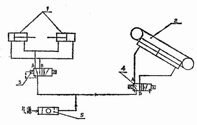
The top fixing base is made of metal instead of plastic that is durable without cracking. And it would hold Mannequin Head very well.
Retractable tripod adjust from 30 in to 55 in. The diameter at stand more stability. A lift rod on the tripod can adjust the height of the middle neck to reach a accurate position. Give you more operation space. Equipped with a multi-functional tray. Making wigs more convenient and efficient
Fit for most training heads, Canvas Block Head, mannequin head, hairdressing training head, Doll Head, and foam head. Suitable for hairdressing students and professional to practice cutting, hair braiding, setting, display styling head, making wigs.